
A prototype part may look correct in a CAD model or appear finished in a physical sample, but that does not necessarily mean it will work as intended. Components may interfere during assembly, moving mechanisms may bind, buttons may fail to actuate reliably, or materials may deform under load. These issues are easier to identify and address before committing to production tooling.
Functional testing uses physical prototype parts to evaluate whether a component or assembly performs its intended mechanical and operational tasks under defined conditions. Depending on the project, testing may involve checking fit and function, verifying critical dimensions, evaluating moving interfaces, assessing structural performance, or integrating customer-supplied electronic components.
The right approach depends on what needs to be validated. Some projects require dimensionally accurate CNC-machined parts, while others can use 3D-printed components for an initial fit check or molded prototypes when material behavior and assembly conditions need closer evaluation. The prototype material, manufacturing process, and test setup should all reflect the specific questions the engineering team needs to answer.
In this guide, we explain how to prepare prototype parts for functional testing, which features and performance characteristics to validate, how to select suitable materials and manufacturing methods, and how to use test results to guide design improvements before full production.
What Are Prototype Parts for Functional Testing?
Prototype parts for functional testing are physical components or assemblies manufactured to evaluate whether a product performs its intended functions under defined conditions. Unlike models created primarily to communicate a product’s appearance, these parts are built to answer specific engineering questions before full-scale production.
Depending on the project, functional prototype parts may be used to check dimensional fit, verify assembly interfaces, evaluate moving mechanisms, test button operation, or assess how a component responds to mechanical loads. For products containing electronics, a prototype enclosure or mechanical assembly may also be evaluated with customer-supplied PCBs, displays, switches, connectors, or other internal components when these are available and included in the project scope.
The level of functional validation depends on the test objective, material properties, manufacturing method, and completeness of the prototype. A 3D-printed housing may be sufficient for an initial fit check, while a load-bearing component may require a material and manufacturing process more representative of its intended operating conditions.
Functional Prototypes vs. Visual Proof-of-Concept Models
Functional prototypes and visual proof-of-concept models serve different purposes, although a single prototype can support both. A visual model focuses on communicating appearance, proportions, and design direction. A functional prototype is developed to investigate whether selected features or mechanisms work as intended.
| Comparison | Functional Prototype | Visual Proof-of-Concept Model |
|---|---|---|
| Primary objective | Validate selected functions and engineering requirements | Communicate appearance, proportions, or a design concept |
| Key evaluation areas | Fit, assembly, movement, operation, and selected performance requirements | Shape, color, surface finish, and visual proportions |
| Material selection | Chosen according to the intended test and required performance | Chosen mainly to achieve the desired appearance |
| Manufacturing considerations | Dimensional accuracy, interfaces, material behavior, and functional features | Surface quality, visual detail, and presentation |
| Typical applications | Mechanism checks, assembly trials, and engineering validation | Design reviews, visual presentations, and appearance approval |
These categories are not mutually exclusive. A prototype can combine a finished exterior with working mechanical features, or it can prioritize functional evaluation while using a simplified surface finish. The right configuration depends on what the team needs to learn from each prototype iteration.
What Should You Validate with Functional Prototype Parts?
Functional prototype testing should begin with clearly defined engineering requirements. Rather than checking every feature without a specific objective, identify the dimensions, interfaces, movements, and operating conditions that could affect how the part performs in the intended assembly.
The validation plan will vary by project. A prototype housing may require dimensional and assembly checks, while a mechanical component may need movement or load testing. For products with electronic components, additional checks may be necessary to verify button actuation, connector alignment, or the interaction between the enclosure and the supplied electronics.
1. Dimensional Accuracy and Fit
Dimensional accuracy is often the first step in functional validation. Measure critical dimensions such as hole diameters, mounting locations, wall thicknesses, mating surfaces, and clearances against the approved CAD model or engineering drawing.
A part can appear visually correct but still fail to fit because of dimensional deviations or tolerance accumulation across multiple components. Check the dimensions that directly affect assembly and operation, and compare the results with the specified tolerances rather than relying on appearance alone.
2. Assembly Interfaces and Fasteners
Check whether the prototype fits together with its mating parts and whether the intended assembly sequence can be completed without unexpected interference. Important features may include screw holes, locating pins, snap fits, mounting bosses, connector openings, and alignment surfaces.
During assembly trials, look for misalignment, excessive gaps, difficult insertion, loose connections, or fasteners that cannot engage correctly. When several components interact, evaluate the assembled condition as well as the individual parts.
3. Buttons, Controls, and User Interaction
For products with buttons, switches, sliders, or other user controls, verify that each feature can be reached and operated as intended. Depending on the design, relevant checks may include button travel, actuation force, return behavior, clearance around moving controls, and interference with the enclosure.
Mechanical operation and electrical response are not the same test. If the objective is to confirm that a button activates a circuit or triggers an electronic function, the prototype must include the relevant switch, PCB, or other required components. These components may need to be supplied by the customer and integrated into the agreed project scope.
4. Moving Mechanisms and Functional Operation
Moving components require checks beyond static dimensions. Hinges, sliding mechanisms, rotating parts, and linked assemblies should be evaluated for their intended range of motion, clearance, smoothness, and potential binding or interference.
Where repeated operation matters, perform a defined number of operating cycles under representative conditions and record any changes in movement, looseness, wear, or performance. A short movement check can identify immediate problems, but it should not be presented as a durability test unless the required cycling procedure has been completed.
5. Structural Strength and Load Response
If a prototype part must support a load, resist bending, or withstand a specified force, define the test conditions before evaluation. Depending on the application, this may involve static loading, controlled force application, deflection measurements, or other engineering tests.
Record the applied load, test duration, observed deformation, and any cracking, loosening, or other failure. The results must be interpreted in the context of the selected material, manufacturing process, part geometry, and acceptance criteria. A prototype made from a different material or process may not represent the performance of the eventual production part.
Functional Prototype Validation Checklist
| Validation Area | What to Check | Typical Evidence |
|---|---|---|
| Dimensions and fit | Critical dimensions, clearances, hole positions, mating surfaces | Measurement records and fit-check results |
| Assembly interfaces | Fasteners, locating features, snap fits, alignment, assembly sequence | Assembly observations and interface checks |
| Buttons and controls | Travel, actuation, return behavior, accessibility, electrical response where applicable | Operation records and switch or circuit checks |
| Moving mechanisms | Range of motion, interference, binding, repeated operation | Movement observations and cycle-test records where required |
| Structural performance | Load response, deflection, cracking, loosening, permanent deformation | Recorded test conditions and measured results |
Not every prototype requires every test. Select the checks that correspond to the product's intended use, critical design requirements, and foreseeable failure modes. Documenting the test conditions and results makes it easier to identify design changes and determine what should be verified in the next prototype iteration.
Once the validation objectives are clear, the next step is to select materials and manufacturing methods that are suitable for the required checks. Learn more about our functional prototype manufacturing services to explore options for producing physical parts for engineering evaluation.
How to Prepare Prototype Parts for Functional Testing
Successful functional testing starts before a prototype part is manufactured. The engineering team needs to define what the part must do, identify the features that affect performance, and establish how the test results will be evaluated. Clear requirements help prevent avoidable revisions caused by missing dimensions, incomplete assembly information, or unsuitable material choices.
Before requesting prototype manufacturing, prepare the available design files, critical dimensions, test objectives, operating conditions, and any components required for assembly. The exact information needed depends on the complexity of the part and the type of validation planned.
1. Prepare CAD Files and Engineering Drawings
Provide the latest approved 3D CAD model and, where available, 2D engineering drawings. Commonly accepted file formats include STEP, STP, and STL, although the preferred format depends on the geometry, manufacturing process, and inspection requirements.
STEP files are generally useful for transferring solid geometry between CAD systems. STL files describe triangulated surfaces and may be suitable for 3D printing, but they do not carry the same parametric design information as a native CAD model. For parts with critical dimensions or precision interfaces, include dimensioned drawings and clearly identify the required tolerances.
Before submission, confirm that the files represent the intended revision and that the relevant mating parts, mounting features, and assembly interfaces are included. If a complete assembly cannot be shared, provide the surrounding geometry or interface dimensions needed to assess fit and clearance.
2. Identify Critical Dimensions and Functional Features
Not every dimension has the same effect on performance. Identify the features that directly influence fit, assembly, movement, or operation, such as mounting holes, shaft diameters, sliding clearances, snap-fit features, connector openings, and button travel.
Specify tolerances for critical dimensions wherever they are known. If the design is still being developed, identify the dimensions that need to be evaluated and discuss any unresolved tolerances before manufacturing begins. This helps the engineering team focus inspection and testing on the features most likely to affect the result.
3. Define the Test Objectives and Acceptance Criteria
State what the prototype needs to prove. For example, the objective may be to confirm that two parts assemble correctly, verify that a hinge moves through its intended range, check whether a button can be pressed without interference, or assess whether a component withstands a specified load.
Where possible, define measurable acceptance criteria before testing. These may include dimensional limits, allowable deflection, required operating force, movement range, or a specified number of operating cycles. If formal acceptance limits have not yet been established, identify the observations or measurements needed to support the design decision.
4. Specify Loads and Operating Conditions
A prototype intended for functional evaluation should be tested under conditions relevant to its intended use. Depending on the application, these may include applied forces, torque, operating speed, temperature, humidity, exposure to particular fluids, or repeated movement.
Describe the expected loads, test duration, operating environment, and any relevant safety limits. A component intended for a light-duty mechanism may require a different validation approach from one that supports a structural load. If the final operating conditions are not yet known, state the assumptions being used so the test results can be interpreted appropriately.
5. Prepare Customer-Supplied PCB and Electronic Components
For products with electronics, mechanical prototype testing may depend on access to the actual PCB, display, switches, connectors, cables, batteries, or other internal components. These items can affect enclosure dimensions, mounting positions, cable routing, connector alignment, button actuation, and assembly access.
Confirm which components will be supplied by the customer and which assembly or verification tasks are included in the project scope. If the prototype needs to demonstrate an electronic response, such as a button activating a circuit, the relevant electronics and any required test setup must be available. A mechanical prototype alone cannot establish that the complete electronic system works correctly.
If electronic components are not yet available, the team may still be able to evaluate selected mechanical features using interface dimensions, reference components, or agreed test fixtures. However, the limits of that validation should be documented.
Functional Prototype Preparation Checklist
| Information or Item | What to Provide | Why It Matters |
|---|---|---|
| CAD files and drawings | Current 3D model, dimensioned drawings, revision details | Defines the geometry and manufacturing requirements |
| Critical dimensions | Key measurements, tolerances, mating interfaces | Focuses inspection on features affecting fit and function |
| Test objectives | Required functions, test questions, acceptance criteria | Determines which checks and measurements are necessary |
| Loads and environment | Forces, torque, temperature, exposure, operating cycles where applicable | Helps establish relevant test conditions |
| Assembly information | Mating parts, fasteners, assembly sequence, interface details | Supports realistic fit and assembly evaluation |
| Electronic components | PCB, display, switches, connectors, cables, or reference dimensions as required | Enables relevant integration and interaction checks |
Confirm the Scope Before Manufacturing
Before production of the prototype parts begins, confirm the required material, manufacturing method, finishing requirements, quantity, inspection needs, and assembly responsibilities. Also clarify whether the project requires physical parts only, basic assembly, or specific functional verification.
If detailed CAD files are confidential, discuss the applicable confidentiality arrangements before sharing them. Provide the information necessary for quotation and engineering review through the agreed secure communication process.
Once the requirements are defined, the next step is to select materials and manufacturing processes that match the intended validation objectives. The appropriate choice depends on the required geometry, dimensional accuracy, material behavior, quantity, and test conditions.
How to Choose Prototype Materials and Manufacturing Processes
The right manufacturing process for prototype parts depends on what you need to evaluate. A prototype intended for appearance review may require accurate color, texture and surface finishing, while a prototype used for functional testing may need to withstand mechanical loads, repeated movement or specific environmental conditions.
CNC machining, 3D printing, vacuum casting and sheet metal fabrication each serve different purposes. The best option depends on part geometry, material requirements, dimensional tolerances, quantity and the tests the prototype must undergo.
| Manufacturing Process | Common Applications | Potential Benefits for Testing | Important Considerations |
|---|---|---|---|
| CNC Machining | Precision housings, brackets, mechanical components and parts requiring defined dimensions or material properties. | Suitable for checking dimensions, mounting features, interfaces and assembly fit. Depending on the selected material, machined parts can also support mechanical testing. | Cost and lead time depend on the material, geometry, machining complexity and required finish. |
| 3D Printing | Complex geometries, internal features, early design iterations and prototypes needed quickly. | Useful for checking form, packaging, initial assembly fit and selected mechanisms before committing to other processes. | Strength, layer bonding, surface quality and heat resistance vary with the printing technology, material and build orientation. |
| Vacuum Casting | Small batches of plastic-like parts, housings, covers and selected flexible or elastomer-like components. | Can provide multiple similar parts for appearance review, assembly evaluation and selected handling or interaction tests. | Casting resins do not necessarily reproduce the properties of production thermoplastics. Material performance and mold life must be considered. |
| Sheet Metal Fabrication | Metal enclosures, brackets, panels, supports and folded structural components. | Useful for checking mounting locations, enclosure dimensions, folded geometry and the fit of metal assemblies. | Bend allowances, material thickness, joining methods and manufacturing tolerances can affect final fit and geometry. |
These processes are not interchangeable in every application. A process that works well for a visual model may not be appropriate for a prototype that must withstand repeated loading, heat or demanding operating conditions.
Match Prototype Materials to Real-World Test Conditions
Material selection should reflect the purpose of the test, not just the appearance of the finished part. Before manufacturing begins, identify the conditions the prototype is expected to experience and decide how closely it needs to represent the intended production product.
- Mechanical loads and repeated use: For snap-fits, hinges, brackets, buttons or load-bearing components, consider stiffness, strength, toughness and fatigue behavior. A material suitable for checking shape may not be suitable for repeated mechanical testing.
- Temperature and environment: If the part will encounter heat, moisture, cleaning agents or other chemicals, check the material's resistance under the expected conditions before using the test results to guide design decisions.
- Dimensions and assembly: For holes, fasteners, mating surfaces and enclosure interfaces, pay attention to dimensional tolerances, finishing allowances and the actual assembly conditions. Surface coatings or paint can also affect fit where clearances are tight.
- Appearance and surface finish: If the purpose is to review color, gloss, texture or the visual quality of a product, the finishing process and reference specifications may be as important as the base material.
- Similarity to the final product: When test results will inform production decisions, use materials and manufacturing conditions that are as representative as practical. Clearly document any differences between the prototype and the intended production part.
Example: Evaluating a Laptop Prototype
A laptop prototype can involve several different evaluation goals. The outer cover may need to demonstrate a specific color and surface finish, while the keyboard area may need to be assessed for layout, component fit and physical interaction. These goals do not necessarily require the same manufacturing process or material.
These examples illustrate why a prototype should be evaluated against clearly defined objectives. The cover may primarily require appearance and finish review, while the keyboard assembly may require fit and interaction checks. If the goal also includes repeated key presses, hinge cycling, thermal performance or structural loading, the prototype materials, internal components and test setup must be appropriate for those additional requirements.
Important: A prototype's appearance alone does not establish its material, manufacturing process or functional performance. Before testing, confirm what the part is made from, how it was manufactured and which requirements it is intended to validate.
Choose the Process Around the Test Objective
Start by defining what you need to learn from the prototype. If the main goal is to evaluate appearance, prioritize color and surface finishing. If you need to check fit and assembly, focus on critical dimensions and interfaces. If you need to assess movement, repeated operation or mechanical performance, confirm that the selected material and manufacturing process are suitable for the intended test conditions.
When the appropriate process is unclear, provide the available CAD files, drawings, material preferences, prototype quantity and test objectives for a manufacturing review before production begins.
Common Functional Tests for Prototype Parts
Functional testing helps determine whether a prototype behaves as expected under defined conditions. The appropriate tests depend on the part's purpose, the design risks being investigated and the requirements it must meet. A housing may need fit and assembly checks, while a moving mechanism may also require motion and repeated-operation testing.
Before testing, identify the features that matter most, define measurable acceptance criteria where possible, and record the test conditions. This makes it easier to compare design iterations and understand whether a result reflects the design, the material, manufacturing variation or the way the test was performed.
| Test Type | What to Check | What to Record |
|---|---|---|
| Fit Testing | Dimensions, clearances, mating surfaces, hole locations and alignment between adjoining parts. | Measured dimensions, observed gaps, interference points and deviations from drawing requirements. |
| Assembly Testing | Assembly sequence, fastener engagement, insert locations, snap-fits and access to installation points. | Assembly difficulties, misalignment, loose or overly tight connections, and any rework required. |
| Mechanical Load Testing | Response to specified forces, pressure, bending or other application-relevant loads. | Applied load, test setup, visible deformation, damage and whether defined acceptance criteria were met. |
| Motion and Operation Testing | Movement range, hinge or slider travel, mechanism interference, button operation and repeated-use behavior. | Motion range, sticking, interference, inconsistent operation and cycle count when repeated cycling is required. |
| Temperature and Environmental Testing | Dimensional changes, material response or operation under specified temperatures, humidity or relevant exposure conditions. | Test duration, environmental conditions, before-and-after measurements, visible changes and functional observations. |
1. Fit Testing
Fit testing checks whether prototype parts match their intended dimensions and interfaces. It is especially useful for enclosures, covers, brackets and components that must align with adjoining parts.
Measure critical dimensions and inspect mating surfaces, gaps, holes and alignment features. For complex metal components, a coordinate measuring machine (CMM) can be used to measure selected three-dimensional features against engineering drawings or CAD data, where the inspection setup and measurement method are appropriate.
Dimensional inspection is only one part of fit validation. Where practical, assemble the components to check for interference, excessive clearance or alignment problems. Parts may meet individual dimensional requirements and still fit poorly when tolerances accumulate across an assembly.
2. Assembly Testing
Assembly testing evaluates how parts come together and whether the intended assembly sequence is practical. Check fasteners, threaded features, locating pins, inserts, snap-fits and access for tools where these features are part of the design.
Record any forced alignment, unexpected gaps, damaged features, loose connections or repeated adjustments. If a prototype uses temporary fasteners, substitute components or simplified internal parts, document these differences because they may affect the results.
3. Mechanical Load Testing
Mechanical load testing checks how a prototype responds to forces that reflect its intended application. Depending on the component, this may involve compression, bending, tension, pressure or a specified load applied at a particular location.
Define the load, direction, application point, duration and acceptance criteria before starting. Observe deformation, cracking, loosening or other changes. Do not assume that a prototype made from a visually similar material will behave like the intended production part.
4. Motion and Operation Testing
For parts with moving or interactive features, check whether the mechanism travels through its intended range without obstruction. Relevant examples include hinges, sliders, rotating components, buttons, latches and movable covers.
Observe sticking, uneven movement, interference, unwanted play and inconsistent operation. If the design requires repeated use, define the number of cycles and inspection intervals in advance. A brief movement check is not equivalent to a durability or life-cycle test.
5. Temperature and Environmental Testing
Environmental testing is appropriate when the prototype will experience conditions such as elevated or low temperatures, humidity, moisture or contact with specific chemicals during its intended use.
Choose conditions that reflect the actual application and the question being investigated. Record exposure time and conditions, then compare relevant dimensions, surface appearance and functional behavior before and after testing. Confirm that the prototype material is suitable for the test; otherwise, the results may not represent the intended product.
Important: Not every prototype requires every test. Select tests according to the intended use, known design risks and project acceptance criteria. Safety-critical, regulated or formal qualification testing may require dedicated equipment, documented procedures and qualified test providers.
Document the Results and Decide What to Change
After testing, record the prototype version, material, manufacturing process, test setup, measured results and any observed failures. Compare the findings with the original acceptance criteria rather than relying only on visual impressions.
If a part fails, identify the likely cause before changing the design. The issue may relate to geometry, tolerances, material selection, manufacturing variation or the test setup itself. Make controlled changes, then repeat the relevant test to determine whether the result improves.
How to Evaluate Functional Prototype Test Results
Functional prototype testing is most useful when the results lead to clear engineering decisions. After each test, compare the observed behavior and measurements with the original requirements. Record any deviations, failures or unexpected results, then translate the findings into specific changes for the next prototype iteration.
Avoid relying only on statements such as "the part fits" or "the mechanism works." Record what was tested, under which conditions, what happened and whether the result met the defined acceptance criteria. This creates a traceable basis for comparing prototype versions and deciding what should change next.
1. Record the Test Conditions and Expected Results
Before interpreting a result, make sure the test conditions are documented. Differences in loads, temperature, assembly setup, materials or measurement methods can affect the outcome and make comparisons between prototype versions unreliable.
| Record Item | What to Document | Example |
|---|---|---|
| Prototype Identification | Part name, drawing number, revision, sample ID and relevant material or manufacturing details. | Housing, Rev B, Sample 03, specified material and process. |
| Test Conditions | Test setup, equipment, applied load, operating conditions, duration and other relevant parameters. | Assembly checked using the specified fasteners and installation sequence. |
| Expected Result | Drawing dimensions, functional requirements, acceptance limits or other criteria established before testing. | The specified clearance must remain within the drawing tolerance. |
| Actual Result | Measured values, observed behavior, photographs and any relevant instrument readings. | Measured clearance, observed interference or recorded movement. |
| Outcome | Pass, fail or inconclusive, with a short explanation and links to supporting evidence where available. | Fail: interference occurred during assembly at the specified interface. |
Use measurable acceptance criteria whenever possible. If the requirement is subjective, such as perceived button feel or surface appearance, define the evaluation method and reference standard before comparing samples.
2. Compare Actual Results with Acceptance Criteria
Evaluate each result against the requirement that the test was intended to verify. For dimensional checks, compare measurements with drawing tolerances. For mechanical or operational tests, compare the observed behavior with the specified load, movement range, operating sequence or other relevant criteria.
- Pass: The result meets the defined acceptance criteria under the recorded test conditions.
- Fail: One or more requirements are not met, or an unacceptable condition occurs during testing.
- Inconclusive: The available evidence is insufficient to make a reliable decision, or the test conditions were not adequately controlled.
A passing result applies only to the requirements and conditions actually evaluated. It does not automatically demonstrate that the entire product is ready for production or that untested operating conditions are safe.
3. Document Deviations and Failure Symptoms
When a prototype does not meet expectations, describe the observable problem before proposing a solution. Include where the issue occurred, when it appeared, how frequently it happened and whether it could be reproduced.
| Observed Issue | Evidence to Capture | Questions to Investigate |
|---|---|---|
| Poor Fit or Interference | Measured dimensions, clearance values, interface photographs and drawing revision. | Is the deviation related to geometry, tolerances, finishing allowance or accumulated variation? |
| Loose or Difficult Assembly | Assembly sequence, fastener details, affected interfaces and observed gaps or resistance. | Are the mating features aligned? Are the fasteners, inserts and assembly method consistent with the requirements? |
| Cracking or Excessive Deformation | Applied load, location of damage, material information and photographs before and after testing. | Could the result relate to material properties, geometry, stress concentration, manufacturing defects or test setup? |
| Inconsistent Movement | Movement range, cycle count if applicable, locations of sticking and repeated observations. | Is there interference, excessive friction, misalignment or variation between components? |
| Environmental Change | Exposure conditions, duration, before-and-after measurements and visible or functional changes. | Is the material suitable for the environment? Were the exposure conditions and measurement methods appropriate? |
Important: A visible failure does not always identify its root cause. Separate the observed symptom from the suspected cause, and verify the cause where practical before committing to a design change.
4. Convert Findings into Specific Modification Requirements
The next prototype revision should address a clearly documented issue, not just a general impression that the design needs improvement. State what needs to change, where the change applies and how the updated part will be evaluated.
| Problem | Modification Requirement | Follow-Up Verification |
|---|---|---|
| Two mating parts interfere during assembly. | Review the affected interface dimensions and revise the relevant geometry or tolerance requirements as justified by the evidence. | Re-measure the interface and repeat the assembly check. |
| A bracket deforms under the specified load. | Investigate material, geometry and load paths, then define an appropriate design or material change. | Repeat the load test under the same documented conditions, where appropriate. |
| A moving part sticks during operation. | Identify the interference or friction source and specify the required geometry, clearance or interface adjustment. | Recheck the full movement range and repeat relevant operation or cycle tests. |
When possible, change one main variable at a time so that the effect of the modification can be evaluated. If several changes are necessary, document them together and identify which tests are needed to verify each affected requirement.
5. Use a Repeatable Prototype Iteration Process
A practical iteration cycle connects test evidence to design updates and then back to verification. Keep the records for each revision so that improvements, recurring failures and unresolved risks remain visible.
- Record: Capture the prototype revision, test setup, acceptance criteria, actual results and supporting evidence.
- Evaluate: Identify which requirements passed, failed or remain inconclusive.
- Investigate: Separate observed symptoms from likely root causes and determine what additional checks are needed.
- Specify changes: Document the affected feature, requested modification and reason for the change.
- Manufacture the next revision: Confirm the updated files, revision identifiers, material and manufacturing requirements.
- Re-test: Repeat the relevant tests and check whether the changes resolved the original issue without introducing new ones.
Functional Prototype Test Review Checklist
Before closing a test round, confirm that the following items have been addressed:
- The tested prototype and drawing revisions are identified.
- Test conditions and acceptance criteria are documented.
- Actual measurements and observed behavior are recorded.
- Deviations and failure symptoms are supported by evidence where possible.
- Modification requests identify the affected features and required changes.
- The next revision has a defined verification plan.
- Unresolved issues and limitations are recorded rather than assumed to have passed.
A structured evaluation process helps turn prototype testing into actionable engineering feedback. By recording results consistently, identifying the cause of failures and verifying each revision, teams can make more informed decisions about design changes and the next stage of product development.
When Do You Need a Functional Prototyping Partner?
A functional prototype project often involves more than producing a physical part. You may need to verify dimensional accuracy, assemble multiple components, evaluate surface finishes or check how a mechanism behaves under specific conditions. When these requirements involve different manufacturing and inspection steps, working with a prototyping partner can help coordinate the process.
A suitable partner should understand what the prototype needs to prove, review the available CAD files and drawings, identify manufacturing considerations and clarify what can realistically be verified with the proposed materials and processes.
What to Look for in a Prototyping Partner
| Capability | What to Confirm | Why It Matters |
|---|---|---|
| Manufacturing Processes | Experience with relevant processes such as CNC machining, 3D printing, vacuum casting and sheet metal fabrication. | The selected process should suit the part geometry, material, tolerances, quantity and intended testing. |
| Dimensional Inspection | Suitable measurement equipment, inspection methods and the ability to check specified critical dimensions. | Measured results help establish whether selected features meet drawing requirements. The inspection method should match the required accuracy and geometry. |
| Surface Finishing | Relevant options for color, gloss, texture, polishing, painting or other specified surface treatments. | Finishing can affect appearance, surface feel, dimensions and the fit of mating components. |
| Assembly Support | Whether the supplier can assemble the specified parts, install customer-supplied components and perform agreed checks. | Assembly review can reveal interference, access problems and interface issues that may not be obvious from individual parts. |
| Confidentiality | How CAD files, drawings, project details and reference materials are handled, and whether an NDA can be arranged when needed. | Clear information-handling procedures help protect sensitive product information throughout quotation and manufacturing. |
Inspection Should Match the Requirements
Ask how the supplier will verify the features that matter to your project. Depending on the component, this may involve dimensional measurements, inspection of critical interfaces or a review of assembled parts. For complex geometry, a coordinate measuring machine (CMM) may be appropriate for measuring specified features against engineering requirements.
Dimensional inspection alone does not establish that a prototype has passed every functional test. If the project also requires load testing, repeated operation, environmental exposure or verification of an electronic assembly, clarify the required scope and how each result will be evaluated.
Clarify Assembly and Confidentiality Requirements Early
If your prototype contains a PCB, display, battery, wiring, sensors or other internal components, establish who supplies each item and who is responsible for installation. Confirm whether the scope includes mechanical assembly, basic interaction checks or other specific verification tasks. These activities should not be assumed to be included in every prototype quotation.
Confidentiality should also be discussed before sharing sensitive technical files. Ask about NDA availability and clarify how project information will be used during quotation, engineering review and manufacturing.
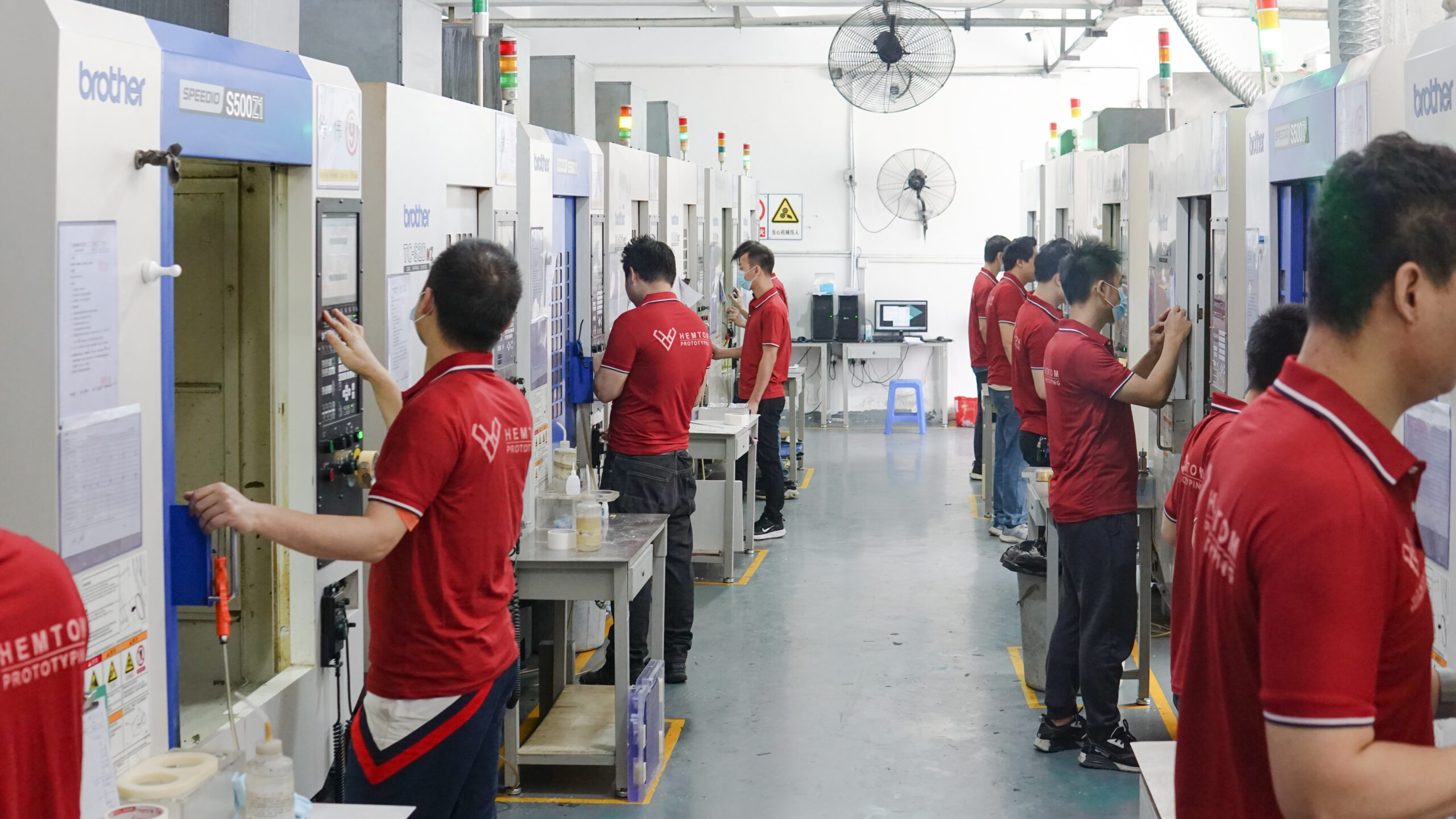
For projects requiring coordinated prototype manufacturing: Explore Hemtom's functional prototype manufacturing services to review the service scope and determine whether it fits your project requirements.
Before requesting a quotation, prepare the latest CAD files or drawings, target material, quantity, surface finish requirements and a short description of what you need to validate. Include any assembly, inspection or confidentiality requirements so the proposed scope can be reviewed accurately.
Frequently Asked Questions
1. How are functional prototypes different from production parts?
Functional prototypes are made to evaluate selected design features, such as fit, assembly, movement, usability or mechanical behavior. Production parts are manufactured under the processes and controls intended for ongoing production.
A prototype may use a different material, manufacturing process or surface finish from the final product. As a result, a successful prototype test does not automatically establish production-level performance. If production behavior needs to be evaluated, choose representative materials and processes where practical, and document any differences.
2. Can functional prototypes be manufactured in small quantities?
Yes. Depending on the part design, material and required quantity, small batches may be produced using CNC machining, 3D printing, vacuum casting, sheet metal fabrication or a combination of processes. The most suitable method depends on geometry, tolerances, finish, mechanical requirements and the number of parts needed.
When requesting a quotation, specify the initial sample quantity and any expected follow-up batches. This helps the supplier evaluate a suitable manufacturing approach without assuming that the prototype process must be identical to mass production.
3. How long does functional prototype manufacturing take?
Lead time depends on part complexity, material availability, quantity, manufacturing process, surface finishing, inspection requirements and assembly scope. A straightforward part may require much less time than a multi-component prototype with custom finishing or integrated customer-supplied electronics.
Ask the supplier to confirm the estimated lead time after reviewing the files and requirements. Clarify whether the estimate includes material procurement, manufacturing, finishing, inspection, assembly and shipping. If design changes are likely, allow time for another manufacturing and testing cycle.
4. Do I need to supply the PCB and other internal components?
If the prototype needs to use a specific PCB, display, battery, sensor, wiring harness or other internal component, confirm the supply responsibility before the project starts. For Hemtom projects, customers should provide the required electronic and internal components when these are not included in the agreed manufacturing scope.
Hemtom can review whether customer-supplied components can be incorporated into the prototype assembly, subject to the project requirements. Confirm component availability, mechanical interfaces, assembly responsibilities and the expected level of functional checking before quotation.
5. Can a supplier assemble a prototype using customer-supplied components?
This may be possible when the supplier has the appropriate assembly capability and the required components, files and instructions are available. Define whether the work includes mechanical installation, fastening, basic wiring or other agreed tasks.
Do not assume that mechanical assembly automatically includes electronics design, PCB development, firmware, software programming or complete product validation. These responsibilities should be explicitly agreed before manufacturing begins.
6. What files should I provide for a functional prototype quotation?
Provide the available 3D CAD files, such as STEP or STP, together with engineering drawings when available. Drawings should identify critical dimensions, tolerances, materials and relevant finishing requirements. Reference images, assembly information and the target quantity can also help clarify the project.
Include a brief explanation of what the prototype needs to validate, such as fit, movement, mechanical loading or interaction with customer-supplied components. If the project is confidential, discuss NDA requirements before sharing sensitive information.
7. Can a functional prototype be used to verify every product requirement?
Not necessarily. The prototype can only provide meaningful evidence for the features, conditions and acceptance criteria actually evaluated. Material differences, simplified assemblies or limitations in the test setup may affect how the results should be interpreted.
Define the test scope before manufacturing and document any requirements that remain unverified. Additional prototypes, more representative materials or dedicated testing may be necessary before making production or qualification decisions.