
Inside Hemtom's Prototype Manufacturing Facility
See where customer CAD files become physical prototypes. Hemtom brings together prototype manufacturing, hands-on finishing, painting, fitting, assembly and inspection within one connected manufacturing workflow.
Turning customer CAD data into physical prototype parts.
Hands-on preparation and finishing of prototype components.
Bringing parts together and checking the completed prototype.
This page focuses on the real manufacturing environment behind Hemtom's prototype work. Explore the workshops, production areas and manufacturing resources involved in turning digital product designs into physical prototypes.
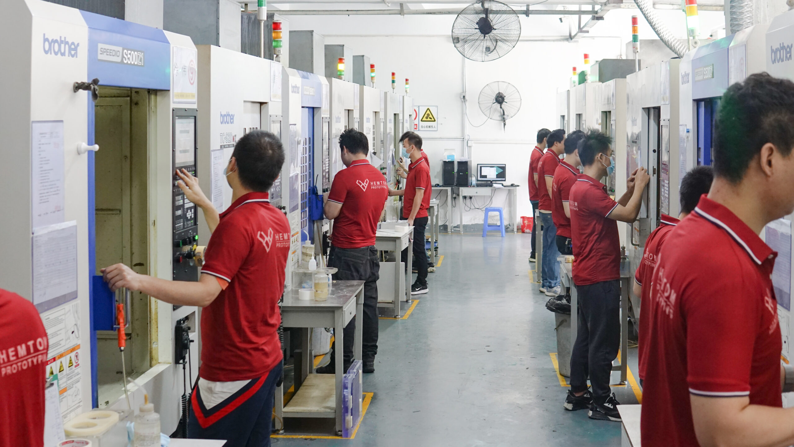
A real view of Hemtom's CNC workshop, with operators working alongside the machining equipment used for prototype production.
CAD
Manufacturing
Assembly
Prototype
Where Digital Product Data Becomes Physical Prototype Parts
Prototype production begins before a physical part appears. Customer CAD data first needs to move into the appropriate manufacturing workflow. At Hemtom, digital manufacturing preparation, CNC machining and 3D printing form part of the process used to turn digital geometry into physical prototype components.

CAD Review & CNC Programming
Customer CAD data and engineering drawings are prepared as part of the CNC machining workflow before prototype parts move into physical production.
Hemtom CNC Workshop
CNC Machining
After manufacturing preparation, CNC equipment is used to turn digital geometry into physical prototype components when CNC machining is the appropriate process for the project.
 3D Printed Prototype Parts
3D Printing
3D printing provides another route from digital geometry to a physical prototype part and can be used where the process is suitable for the geometry, material and purpose of the project.
 Hands-On Post-Processing
3D Printed Part Post-Processing
Printed prototype parts can require hands-on post-processing after printing. The work shown here is part of preparing a printed component after it leaves the printing stage.
CNC machining and 3D printing are different manufacturing routes, not consecutive steps that every prototype must follow. The manufacturing route depends on the individual project's geometry, material and prototype requirements. A multi-part prototype may also bring together components produced through different processes.
Engineering Data
Preparation
or 3D Printing
Prototype Parts
CNC machining is one of the physical manufacturing routes used for prototype production at Hemtom. The next section takes a closer look inside the CNC workshop and the real production environment behind CNC-machined prototype parts.
CNC Prototype Manufacturing in Production
After CAD data has been prepared for manufacturing, the project moves from digital information into physical production. Inside Hemtom's CNC workshop, operators work directly with the machining equipment used to produce prototype components. The actual machining route depends on the individual part, material and project requirements.

Manufacturing Happens at the Machine
CNC production combines digital manufacturing data, machine setup and physical material removal. Operators work with the machining equipment as customer geometry is translated into physical prototype components.

From Digital Geometry to Machined Prototype Components
CNC machining is used when it is appropriate for the prototype's geometry, material and intended evaluation. The photographs above show two different parts of the real production environment: operator interaction with the machining center and material being physically machined inside the equipment.
CNC production includes direct operator interaction with the machining equipment.
Cutting tools machine the material to form the required physical geometry.
Machined parts can then move into the next required stage of the prototype workflow.
Preparation
& Operation
Machining
Component
Machining creates the physical component, but that is not always the end of the prototype process. Depending on the project, manufactured parts can continue into manual preparation and finishing before later fitting, assembly or appearance finishing.
Hands-On Work After the Manufacturing Stage
Producing a prototype part is not always the end of the manufacturing process. Depending on the project, machined or printed components can move into hands-on preparation before later finishing, fitting or assembly. At Hemtom, this work is carried out by technicians directly on physical prototype parts.

Physical Parts Continue Beyond the Machine
Once a component has been physically manufactured, technicians can continue working directly with the part when the prototype requires additional preparation before the next stage.
Technicians handle individual prototype components as they move through the required manual work.
Manual preparation can form the bridge between manufacturing and later finishing, fitting or assembly.
The hands-on work required depends on the individual part and the intended prototype result.
Detail Work on Individual Components
Some prototype components require localized hands-on work after manufacturing. The photograph shows a Hemtom technician manually working on a physical part, illustrating the human stage that can follow machine production.

A Practical Stage in Building a Finished Prototype
A prototype can pass through both machine-based and manual stages. Manufacturing creates the physical geometry; hands-on work can prepare that physical part for what comes next. The exact amount of manual preparation varies from project to project.
CNC machining or another manufacturing process creates the initial physical component.
Technicians work directly with the part where additional preparation is required.
The prepared component can then continue according to the needs of the prototype project.
Manufacturing
& Hands-On Work
or Assembly
When a prototype requires a finished visual surface, prepared components can continue into painting and appearance finishing. The next section shows the physical area where this part of the prototype workflow takes place at Hemtom.
Where Prepared Prototype Parts Take on Their Finished Appearance
Some prototypes are built primarily to evaluate form, fit or function. Others also need to communicate how the final product is intended to look. When appearance finishing is required, prepared prototype components can continue into Hemtom's hands-on painting and finishing workflow.

Appearance Is Built After the Part Is Made
Manufacturing establishes the physical component. When a project also requires a finished visual surface, the part can move through additional preparation and painting according to the prototype's appearance requirements.
Appearance finishing takes place after the required prototype component has been manufactured and prepared.
Technicians work directly with physical prototype components during the painting stage.
Appearance work is applied when required by the individual prototype rather than being a mandatory stage for every part.
When a Prototype Also Needs to Communicate Appearance
A manufactured part can demonstrate geometry, but some prototype projects also need a more developed visual result. Painting and appearance finishing add another stage to the physical prototype workflow when that visual evaluation is part of the project goal.
The prototype component is manufactured before appearance finishing begins.
Parts can require preparation before moving into the appearance-finishing stage.
Painting can form part of the workflow when the prototype requires a developed visual surface.
Prototype Part
Preparation
Appearance Finishing
Component
This factory page shows where appearance-finishing work takes place within the overall prototype manufacturing environment. Detailed finishing methods, surface preparation, color and visual requirements are covered separately as part of Hemtom's surface-finishing expertise.
A prototype often consists of more than one manufactured component. After the required parts have been produced and prepared, the project can move into fitting and assembly where components are brought together into a more complete physical prototype.
Bringing Individual Prototype Parts Together
Many prototypes are made from more than one physical component. Once the required parts have been manufactured and prepared, they can move into fitting and assembly. This is where individual components begin to come together as a more complete physical prototype.

From Digital Product Data to Hands-On Prototype Work
Prototype assembly is a physical stage. Technicians work directly with manufactured components as individual parts are fitted and brought together according to the project's requirements. Digital product data can remain available as a reference while work continues on the physical prototype.
CAD information provides a digital reference for the physical prototype geometry.
Technicians work directly with manufactured prototype parts at the workstation.
Individual components can be fitted and brought together as the prototype takes physical form.
Hands-On Work Across Multiple Prototype Components
Prototype projects can involve multiple separate parts and repeated hands-on work at the component level. This production image shows technicians working directly with physical prototype components in Hemtom's earlier workshop environment.

A Prototype Can Bring Different Parts Together
Different components within the same prototype may require different manufacturing or finishing routes before they come together. Fitting and assembly provide the stage where those individual physical parts are brought into the intended prototype configuration.
Components can arrive from manufacturing and finishing as separate physical parts.
Parts are physically brought together according to the required prototype configuration.
Components are assembled into a more complete prototype when the project requires it.
Parts
Components
Assembly
Integration
Prototype
When required by the project, customer-supplied PCBs or electronic components can be installed as part of prototype assembly. This allows the physical prototype structure to be built around components required for the customer's evaluation.
Hemtom focuses on prototype manufacturing and assembly and does not provide PCB design or PCB manufacturing.
Manufacturing, finishing and assembly create the physical prototype. Inspection provides another stage in the factory workflow before the completed work moves forward. The next section shows the real inspection environment at Hemtom without replacing the more detailed Quality Control process covered separately.
Inspection as Part of the Manufacturing Workflow
Manufacturing a prototype is only part of the factory workflow. Physical components also need to be reviewed as the project moves toward completion. At Hemtom, inspection forms part of the process around the manufactured prototype rather than existing separately from it.

Checking the Part in the Physical World
Once a component exists as a physical part, inspection can move beyond digital geometry and take place directly on the manufactured prototype. The image shows a Hemtom technician using a caliper during physical measurement.
Manufactured components can be measured directly using appropriate inspection tools.
Inspection can take place on individual prototype components as part of the manufacturing workflow.
The checks required depend on the geometry, purpose and requirements of the individual prototype project.
Inspection Connects Manufacturing With the Completed Prototype
Different projects require different checks, and inspection can take place at different points in the manufacturing process. On the factory page, the important point is that inspection is connected to the real physical work being produced.
Physical parts provide the basis for direct dimensional and physical review.
Appropriate checks are carried out according to the needs of the prototype project.
Inspection supports the project as physical components move toward completion.
Manufacturing
Preparation
Assembly
Inspection
This factory page shows inspection as a real part of Hemtom's manufacturing environment. Detailed dimensional, appearance, fitting, assembly and final-review practices belong to Hemtom's dedicated Quality Control page.
People and processes form one part of the manufacturing environment. The next section brings together the equipment and production resources that support Hemtom's prototype manufacturing work.
Manufacturing Resources Behind the Prototype
Different prototype projects can require different manufacturing routes. Hemtom brings together CNC machining, 3D printing, finishing and inspection resources to support the transition from customer CAD data to physical prototype components.

CNC Machining Equipment on the Production Floor
CNC machining is one of the physical manufacturing routes available for Hemtom prototype projects. Multiple machining resources support the production of prototype components according to the geometry, material and requirements of the individual project. The appropriate manufacturing route is selected according to the part rather than applying one process to every project.
Different Equipment for Different Prototype Requirements
A prototype can involve different geometries, sizes, materials and finishing requirements. The resources below show several of the real equipment categories that support Hemtom's prototype manufacturing workflow.

DMG MORI DMU 50
The DMU 50 forms part of Hemtom's CNC machining resources, supporting the manufacture of prototype components where its machining capabilities are appropriate to the individual part. Equipment selection depends on the actual prototype geometry and manufacturing requirements.

3D Printing Equipment
3D printing provides another route for turning digital geometry into physical prototype parts and can be used when it is appropriate to the project's geometry and validation needs.

Larger-Part CNC Machining Resource
Additional CNC equipment provides manufacturing options for prototype components that require a larger working range than smaller machining resources.

Laser Marking
Laser marking equipment supports project-specific surface details, markings or graphics when these are required as part of the completed prototype.

Painting Resources
Dedicated painting resources support prototype appearance finishing when a project requires painted surfaces as part of the intended visual result.
Equipment Is Selected Around the Prototype
This is not a fixed sequence of machines that every prototype follows. Equipment and processes are selected according to the geometry, material, size, surface requirements and purpose of the individual prototype. A multi-part project can also bring together components produced through different manufacturing routes.
CNC resources turn material into physical prototype components.
3D printing provides another route from digital geometry to parts.
Painting and detail-processing resources support finished appearance.
Measurement resources support inspection of manufactured components.

Coordinate Measurement Equipment
Manufacturing resources extend beyond equipment used to make the part. Hemtom also has dedicated measurement equipment that can support dimensional inspection of physical prototype components when required. Detailed inspection methods and quality-control practices are covered separately on Hemtom's Quality Control page.
Hemtom's prototype manufacturing environment combines manufacturing equipment, technicians, hands-on finishing, painting, fitting, assembly and inspection according to the needs of each project. Together, these resources support the path from customer CAD data to a physical prototype.